Quantcast
Channel: Power management
Viewing all 437 articles
Browse latest View live

DC/DC converter datasheets - Calculate system losses

$
0
0

Welcome back to the DC/DC converter datasheets blog series. In this final installment, I will discuss DC/DC regulator component conduction losses.

Conduction losses are a result of device parasitic resistances impeding the DC current flow in a DC/DC converter. These losses are in direct relationship with the duty cycle. When the integrated high-side MOSFET turns on, the load current flows through it. The drain-to-source channel resistance (RDSON) causes power dissipation, which can be expressed as Equation 1:

For nonsynchronous devices like the LM2673, the diode is forward-biased when the integrated MOSFET turns off. During this time, the inductor current ramps down through the output capacitors, the load and the forward-biased diode. Since the load current is now conducting through the diode, there will be power dissipation in it, expressed as Equation 2:

Where, VF is the forward voltage drop of the chosen diode.

In addition to the conduction loss in the integrated MOSFET and the catch diode, there are conduction losses in the inductor as well because every inductor has a finite DC resistance (DCR), which is the resistance of the wire in the coil. Equation 3 expresses the dissipation in the inductor as:

The conduction losses depend on the load current. With heavier loads, the conduction loss in the MOSFET increases and is the dominating factor. Conduction losses plus switching, driver and internal low-dropout regulator (LDO) losses lead to a considerable generation of heat and increase the junction temperature of the integrated circuit (IC). Equation 4 expresses the increase in junction temperature as:

where ICTjis the junction temperature of the IC, TA is the ambient temperature, θJA is the junction-to-air thermal resistance and ICPd is the total power dissipation just in the IC equal to .

The RDSON of the MOSFET typically has a temperature coefficient (RdsonTco). With an increase in the junction temperature of the IC, the RDSON would increase above the nominal based on the temperature coefficient. While this parameter may not be available in the data sheet, TI’s WEBENCH® Power Designer software has that information and uses it for calculating the design efficiency, thus making the results accurate. Equation 5 can adjust the RDSON based on the junction temperature:

where RdsonNom is the nominal value of RDSON as listed in the data sheet.

The increase in RDSON depends on how well the device is heat-sinked and on the junction temperature of the device. Improper heat-sinking can lead to a drastic increase in RDSON and cause a larger dip in efficiency at full load. This is evident in situations when the die attach paddle (DAP) of the IC is not well soldered to the board.

Calculating losses is an iterative process. You will need to evaluate the junction temperature and the resulting RDSON on every iteration of calculating the IC power loss to get accurate results in efficiency. WEBENCH Power Designer takes care of this; it displays the calculated results of passive component losses as well. Knowing these losses is important because it will help you choose the right components, along with a DC/DC regulator that will help maintain good efficiency. The total conduction losses can now be expressed as Equation 6:

Looking over all of the losses, Equation 7 adds them up to calculate the total loss:

Equation 8 expresses the resulting efficiency of the DC/DC regulator design as:

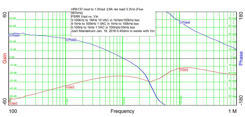
Figure 1 shows the overall efficiency against the load-current curves of the LM2673 taken at different input voltages. You can see that at light loads the efficiency deteriorates; from parts 1 and 2 of this series, you know to attribute this to the switching losses and the losses in the driver and LDO, respectively. Also notice that at the maximum load current, the efficiency at a higher input voltage (VIN) is lower because of the higher switching losses that occur at such voltages. The low VIN efficiency at loads above 1A is comparatively higher because of the reduced switching losses.

 Figure 1: LM2673 efficiency

This ends my three-part blog series on reading and understanding efficiency in data sheets. Now you should be able to understand the different component losses that take place in a DC/DC regulator design. Based on your application needs, you can now make informed decisions when selecting DC/DC regulators, their switching frequency, amount of required board space for heat-sinking, and also when selecting passive components like the diode and the inductor. Select a SIMPLE SWITCHER DC/DC regulator and start a design now in WEBENCH Power Designer.

Additional resources


An easy-to-assemble power supply for optical modules

$
0
0


Optical modules are probably not the first system you might think of in the telecom infrastructure market. Because they’re so small, optical modules easily get forgotten – especially when compared to the larger base stations that you see everywhere when driving down the road. However, both systems do have something in common: they must be robust and reliable in order to minimize network downtime.

Base stations and optical modules are space-constrained – cramming a whole lot of power, processing and functionality into a limited space – although optical modules are generally more pressed for printed circuit board (PCB) space because of their super-small form factor. Finally, both designers of base stations and optical modules value the ease of assembly that comes with integrated circuits (ICs) packaged in traditional quad flat no-lead (QFN) packages. It is generally not desirable to employ wafer-chip scale packages (WCSPs), because they require more complex manufacturing. They also have poorer thermal performance and a corresponding greater temperature rise, which reduces reliability.

The increasing data rates and channel counts in optical modules demand ever-higher currents and new architectures to maintain a small solution size, especially for rails that need currents above 3A. And with currents this high, thermal performance and reliability are issues once again. How much heat can you dissipate in a small optical module? If you can’t dissipate it all into the ambient environment, how hot will the IC get, and will that be too hot? How can new solutions deliver the higher currents while at the same time being small, robust and easy to assemble?

The first step in achieving smaller size for a power supply is to increase the switching frequency. But this also increases the power loss and temperature rise. Fortunately, frequency is not the only knob you can turn to get smaller. Splitting the high current into two lower-current phases allows you to use two smaller inductors rather than one larger inductor. This saves cost and PCB space while increasing efficiency. Read my blog, Are two inductors are better than one?, to learn more about this topic. Higher efficiency also means there’s less heat to dissipate, which eases thermal challenges. I’ll talk more about this in a minute.

In addition to size, robustness is a key optical-module trait. One way to obtain robustness in an optical module is for the module itself to check the performance of the data signal and report a maintenance need or outright system failure. Robustness is also possible when the host processor self-adjusts to optimize its performance. A power-supply IC such as the TPS62480 assists with this in two unique ways: voltage margining and thermal monitoring.

A voltage select (VSEL) pin enables a simple change of the output voltage between two customizable levels. The host processor toggles the VSEL pin to change the output voltage to compensate for its strong or weak silicon, or to adjust its performance for different operating modes. Both of these enable a power-consumption reduction in the module, which reduces the corresponding temperature rise.

If the temperature rise in the TPS62480 power supply is still too high, its thermal-good (TG) feature acts. If the temperature gets near the IC’s maximum rating, the TG pin goes low to alert the host processor. Once the host processor receives this early-warning signal, it can reduce the processing power or data rate, or notify the system host of a possible maintenance issue. Figure 1 shows the typical schematic that includes the VSEL and TG features.

Figure 1: The TPS62480 provides a VSEL pin to easily adjust the output voltage between two levels, as well as a TG pin to alert the host of an elevated temperature

Finally, the TPS62480 is packaged in a QFN-style, easy-to-assemble HotRod™ package. This innovative packaging technology fits a 6A power supply into a 2.5mm-by-3mm package and delivers a total solution size of less than 80mm2. Because it’s like a standard QFN, the package’s thermal resistance is low – and a low temperature rise results. Combined with the high efficiency of the two-phase approach, the low temperature rise enables operation at full power above 85°C ambient with no derating. Figure 2 shows the derating curve.


Figure 2: The TPS62480’s high efficiency and good thermal performance enable its full 6A output current even above an 85°C ambient temperature

Optical modules now have the opportunity to achieve the higher-current power supply required, along with small size, robustness and ease of assembly.

Additional resources:

Learn more about TI's buck converters. 

See how optical switches can handle more data in a smaller footprint in the Precision Hub post: 96 DAC channels in one device! Why would we do that?


Power Tips: Calculate an R-C snubber in seven steps

$
0
0

Ringing in switching power supplies can generate radiated and conducted noise, create circuit jitter and excessive dissipation, and easily overstress components. Ringing is a major concern in applications such as audio, processor power and any design that requires electromagnetic interference (EMI) qualification.

Often, you can tame the circuit by adding a simple resistor-capacitor (R-C) snubber to “damp out the ringing.” In this post, I’ll outline a seven-step procedure that can help take the guesswork out of selecting your snubber values.

Ringing can occur in any switching converter where an inductance and a capacitance form an inductor-capacitor (L-C) tank. The inductance may be from component leads, printed circuit board traces and transformer leakage, while the capacitance may be due to nonlinear components such as rectifiers and interwinding transformer capacitance. The ring frequency and amplitude are generally unknown since most circuit parasitics are typically unknown. Two common locations where excessive ringing occurs (at least in converters such as a flyback) are across the rectifier diode and the switching FET. One simple solution to reduce this ringing is by damping or “snubbing” it with a series R-C circuit, typically placed directly across the rectifier or FET.

The seven-step procedure shown in Table 1 uses a common methodology that shifts the resonant frequency of the ringing to calculate the circuit’s parasitic capacitance (Co) and inductance (L). Once you know those, you can calculate the snubber capacitor (Csnub) and resistor (Rsnub). I took the example waveforms in Figures 1 and 2 with an R-C snubber placed in parallel with the rectifier in the 9Vdc-57Vdc Input, 56V/20W Isolated Flyback Reference Design, but the procedure is the same if used across the FET. 

Figure 1: Unsnubbed rectifier ringing (top) and frequency-shifted ringing (bottom)


Figure 2 shows the spike reduction and damping effect of the calculated values. You can adjust the ringing higher or lower by varying the Csnub value. Larger values for Csnub reduce the voltage-spike amplitude further, but increase power loss in Rsnub.

Alternatively, you can decrease the power dissipation in Rsnub by lowering Csnub, but ringing will increase. You must weigh the trade-off between acceptable voltage-ring amplitude and Rsnub losses.


Undamped ringing in switching converters can create excessive EMI and overstress components. A properly calculated R-C snubber can be instrumental in taming these issues. I hope you’ll find my seven-step procedure simple to follow and a good starting point to help you damp out the ringing. For more about the topic covered here, see my EETimes Power Tips post “Calculating an R-C snubber.”  

Optimizing voltage accuracy

$
0
0

Whether it’s shooting darts or hitting a golf ball, accuracy matters. The same is true of a power supply –and it’s especially true when powering an ASIC, FPGA or any high-end processor. Simply put, the supply-voltage ranges of FPGAs and processors are becoming increasingly narrow.

Figure 1 is an example FPGA data sheet. The supply-voltage range for two supply rails, VCCINT and VCCBRAM, is 0.95V ±30mV for a particular model. That’s just slightly more than a ±3% tolerance. Making things worse, this voltage range shrinks when voltage monitoring and/or protection are introduced. As a result, the power supply could now be required to be 1% accurate or better to avoid a false trip.

Figure 1: Recommended operating conditions of an example FPGA

Such limited range demands a correspondingly accurate power supply design. Although switched-mode power supplies are a typical choice for powering these loads, recent advancements have made low-dropout linear regulators (LDOs) attractive options as well. TI’s recently released TPS7A84 and TPS7A85 are 3A and 4A LDOs that combine high power supply rejection ratio (PSRR), low dropout and wide input-voltage ranges, making them ideal for minimizing voltage ripple. For this discussion, it’s the accuracy of these LDOs that make them compelling solutions to power FPGAs and processors. In this post, I’ll illustrate how to navigate the nuances of voltage-rail accuracy and how a performance LDO meets stringent accuracy requirements while minimizing total solution size and output capacitance.

DC accuracy

In order to generate a voltage rail within the supply tolerance specified for a particular FPGA or processor, you must consider both the DC and AC output accuracy of the regulator. Of the two, it’s often easier to approximate DC accuracy. The main factors governing DC accuracy are:

  • Variations in temperature.
  • Variations in input voltage.
  • Variations in load current.
  • External resistor-divider tolerance.

Fortunately, the impact of these variations on accuracy (with the exception of external resistor-divider tolerances) is usually specified in the electrical characteristics table of a given voltage-regulator data sheet. Take the TPS7A85 datasheet. Output voltage accuracy is specified at a maximum of 1% when incorporating variations in load current, input voltage and temperature, as shown in Figure 2. (In fact, the output accuracy is even capable of reaching a maximum accuracy of 0.75% under certain conditions.) Characterizing accuracy in this way gives you an idea of the worst-case scenario.

Figure 2: Output voltage accuracy of the TPS7A85

Of course, you can examine the relationship between these various factors and output accuracy independently. The electrical characteristics table and typical characteristics curves show individual specifications and plots for line and load regulation. Consulting these sections provides a better idea of how a particular set of conditions will affect output accuracy in an application.

External resistors and ANY-OUT operation

Although data-sheet accuracy specifications don’t incorporate external resistor-divider tolerances, they can still affect accuracy significantly. You can minimize the effect of such inaccuracy by either selecting tighter tolerance resistors (0.1% or less) or opting for a fixed-output voltage regulator (which has factory-trimmed, internal feedback resistors).

There is, however, a way to retain adjustability while also eliminating the compromised accuracy associated with external resistors. ANY-OUT operation allows you to set your desired output voltage by grounding a specific combination of ANY-OUT pins. Figure 3 shows an example of this operation where the TPS7A85 is programmed to output 3.3V by grounding the 100mV, 800mV and 1.6V pins.

Figure 3: Using the TPS7A85’s ANY-OUT pins to program the output to 3.3V

Adding the values of these pins to the reference voltage (0.8V) gives a sum of 3.3V:

The benefit of ANY-OUT operation is that it allows you to adjust the output voltage without incurring inaccuracy stemming from external resistors. In other words, 1% accuracy is the worst-case scenario no matter how you program the output voltage. In fact, you can adjust the output voltage dynamically via the ANY-OUT pins. For more about this subject, see the application report, “ANY-OUT™ Low-Dropout Regulator Controlled by I2C IO Expander Device.”

AC accuracy

AC accuracy also plays a large role in determining overall output accuracy. As with DC specifications, many FPGA and processor data sheets also specify maximum tolerable transient deviations from the normal supply range in terms of amplitude and duration. Dynamic shifts in LDO input voltage or load current can cause the output voltage to ring before the internal loop stabilizes. The amplitude and length of this ringing is contingent on a variety of factors, including internal topology, the input capacitor, the output capacitor and slew rate.

Load transient response is usually much more pronounced than that of line transients, especially when sourcing 3A or more. As such, the TPS7A85 data sheet details the load transient response under a variety of conditions. Figure 4 shows the load transient response as a function of output capacitance.

Figure 4: Load transient response vs. output capacitance

As shown in Figure 4, increasing output capacitance helps dampen the amplitude of the ringing, which is necessary to prevent the output from deviating outside the permitted supply-voltage range of a given FPGA or processor. Of course, adding bulk output capacitance also takes up coveted space on a printed circuit board (PCB). The TPS7A84 and TPS7A85 ease this dilemma by having a wide-bandwidth control loop that responds quickly to dynamic load changes. As such, you can mute ringing with less output capacitance. The result is a solution size that is much more compact – the TPS7A85 is only 3.5mm by 3.5mm, after all.

Putting it all together

Meeting the tight supply-voltage requirements of FPGAs and processors requires that you consider both DC and AC conditions. Performance LDOs have the ability to maintain DC accuracy of 1% or better across a variety of conditions. These LDOs also feature the excellent transient response necessary to subdue ringing associated with quick load changes. By combining these two advantages with the ability to filter switching noise, the TPS7A84 and TPS7A85 represent two solutions that can put your mind at rest when constructing a power scheme.

Be sure to subscribe to the Power House blog to receive more power management tips and insights.

eFuses: clamping and cutoff and auto retry, oh my! – part 1/3

$
0
0

Much like when Dorothy arrived in Oz, your first look at the multitude of features inside the Texas Instruments eFuse portfolio can be overwhelming. With options such as voltage clamping, circuit breaking and auto retry (to name a few), our portfolio can help protect almost every power circuit.

But with so many choices, picking the perfect eFuse can pose a challenge. The goal of this three-part blog series is to simplify your eFuse selection process by removing the confusion surrounding the options for overvoltage (part 1), overcurrent (part 2) and fault response (part 3).

We’re off to see the wizard down the yellow brick road of circuit design.

As you begin your journey down the Yellow Brick Road, you come to the first fork: overvoltage protection (OVP). Figure 1 shows two options: output-voltage clamping and output-voltage cutoff. Before deciding which path to go down, let’s take a look at the benefits of each, starting with the simpler and more common of the two options: output-voltage cutoff.

The benefits of output-voltage cutoff

An eFuse with output-voltage cutoff will generally have an OVP pin where an external resistor can set the trip point. As an example, let’s set the trip point to 15V. During normal operation, a 12V rail will not trip the comparator, and the internal FETs will remain closed; the device will stay on. However, a transient of 18V will exceed the trip point and the internal FETs will open, turning the device off. Figure 1 shows this operation.

Figure 1: eFuse output-voltage cutoff example using the TPS25940

Once the input voltage (VIN) exceeds 15V, the eFuse turns off and the output voltage (VOUT) falls to 0V, as shown in Figure 1. The eFuse will remain off as long as the input voltage exceeds the set overvoltage trip point. Once the input voltage returns to 12V, the device turns back on and VOUT once again returns to 12V. Because output-voltage cutoff disables the eFuse when active, it will never trigger a thermal shutdown.

While this is the most common form of overvoltage protection in the Texas Instruments eFuse portfolio, it may not always be the best. Sometimes it is beneficial to keep a voltage rail alive for as long as possible by clamping the output voltage to the nominal voltage.

The benefits of output-voltage clamping

Contrary to output-voltage cutoff, during output-voltage clamping the eFuse remains operational. When the input voltage exceeds the hard-coded trip point, the internal clamp will activate and limit the output voltage. As shown in Figure 2, the TPS25924 eFuse integrates a 15V output clamp.

Figure 2: eFuse output-voltage clamping using the TPS25924

You can see in Figure 2 that when the input voltage spikes from 12V up to 18V, the clamping circuitry activates and ensures that the eFuse only outputs 15.6V (typically 15V). If the transient on the input is only temporary, this can allow the eFuse to “hide” the fault from downstream circuitry. If the fault lasts long enough to activate the eFuse’s thermal shutdown (typically TJ = 150°C), then the fault will still cause the eFuse to turn off (similar to output-voltage cutoff). After thermal shutdown, all eFuses then enter one of two fault-response modes: either latch off or auto retry, both of which I will cover in the third part of this series.

But first, stay tuned for part 2, which will delve into overcurrent event-response options: current limiting and circuit breaking.

Additional resources

Keeping up with the standards: Efficiency and standby power requirements

$
0
0

Energy agencies around the world are concerned about growing power consumption and the amount of available deliverable energy. One of the largest demands on the world’s power grid comes from external power supplies (EPSs); these include laptop adapters and phone and tablet USB chargers/adapters. Portable electronics users probably use two to three EPSs every day.

To help conserve energy and reduce waste, these agencies created initiatives and legislation to compel power-supply designers to develop offline power supplies with higher efficiency and lower standby power. The most popular standards for EPSs are the European Code of Conduct (CoC) EPS V5 Tier 2 energy-efficiency standard and the U.S. Department of Energy (DoE) EPS Level VI efficiency standard. The CoC standard is voluntary; however, a majority of power-supply manufacturers in the European Union (EU) are ensuring that their designs meet its requirements anyway. The DoE efficiency standard is mandatory.

Both standards segregate their requirements into power and voltage ranges. In this post, I’ll focus on the low-voltage (<6V) and lower power (<250W) efficiency and standby power requirements.

Tables 1 and 2 list the CoC and DoE standby power requirements for low-voltage/low-power EPSs. You can see that the EU’s voluntary specifications are slightly stricter than the DoE’s mandatory specifications. Designers generally use flyback converters as offline power converters in this power range. The more traditional fixed-frequency pulse-width-modulated (PWM) controllers with higher integrated circuit (IC) standby current would have difficulty meeting either specification. The power dissipation caused by the trickle-charge bootstrap resistor when starting up these older PWM controllers alone could cause the design to fail the standby power requirements.

Table 1: CoC Tier 2 EPS Low Voltage, Standby Power Requirements

Table 2: DoE Level VI EPS Low Voltage, Standby Power Requirements

To meet these needs PWM manufacturers like Texas Instruments have developed ICs with lower standby current, which enable the use of higher-impedance trickle-charge resistors to reduce standby power (the UCC28704). They have also developed green startup circuitry internal to the PWM controller (the UCC28730) that only dissipates power on initial power up, also reducing standby power.

Plus, primary-side regulated controllers, such as the UCC28704 and UCC28730, regulate the output through the primary to secondary transformer turns ratio and do not require opto-isolator feedback, reducing standby power even further.

In the past, designers would focus on the maximum load efficiency and not spend much time evaluating overall efficiency. This is mostly because of the power-dissipation and power-density requirements. To help increase EPS overall efficiency, the CoC has specifications for four-point efficiency and 10% load efficiency (Table 3). The average efficiency is based on the average of the efficiencies of the power supply taken at 25, 50, 75 and 100% loads. As I mentioned earlier, the DoE average efficiency standard (Table 4) is not as stringent as the CoC standard, and does not include a 10% load efficiency requirement. The DoE standard does calculate average efficiency at the same load points as the DoE.Please note In Tables 1 through 4, the variable Pno stands for the power supply’s nameplate output power. A traditional fixed-frequency flyback converter would have difficulty meeting these efficiency standards, mostly due to switching losses.


Table 3: CoC Tier 2 EPS Low Voltage Average and 10% Efficiency Specifications


Table 4: DoE EPS Low Voltage Average efficiency Specifications

To help meet efficiency requirements in the 1W-25W range, flyback controllers have been designed with FM/AM/FM modulation schemes These controllers modulate the converter’s switching frequency (FM) and primary peak current (AM) in order to control the offline converter’s duty cycle, reducing the power converter’s average switching and conduction losses. To help improve efficiency even further, these controllers use valley switching to reduce switching losses.

In the 25W-250W range, designers generally use quasi-resonant flyback controllers. These controllers are inherently soft switching, with reduced switching losses. Some of these controllers will have burst-mode operation and power-management capability to improve overall efficiency and reduce standby power. One example of power management is to turn off the power factor correction (PFC) pre-regulator at light loading, a feature that some flyback controllers have. PFC is not required below 75W, and turning it off will improve system efficiency below 75W and reduce standby power.

As the world consumes more and more power, being compliant with the EPS V5 Tier 2 and the U.S. (DoE) EPS Level VI efficiency standards becomes imperative. PWM controllers with lower standby current can help reduce stand by power.

Be sure you’re meeting the standards and learn more about TI’s PWM controllers. 

How LDOs contribute to power efficiency

$
0
0

Low-dropout regulators (LDOs) are widely recognized for their low noise and high power-supply rejection ratio (PSRR). However, LDOs can also contribute to power efficiency when they are complemented with the right technique. You can design a low-noise and lean power supply by pairing low-quiescent-current LDOs with appropriate power-saving techniques such as dynamic voltage scaling (DVS) or power cycling. In this blog post, I’ll present some common power-savings techniques.

DVS methods

Mixed-signal processors such as microcontrollers (MCUs), MPUs and digital signal processors (DPSs) demand a high power supply during high-frequency processes, yet only require a fraction of that power during low-power modes or long sleep cycles. You can improve power dissipation by adjusting the voltage-supply levels accordingly to the demand. Let’s review a few popular DVS techniques and their respective technical resources.

  • LDO pair for dual, switchable voltage levels. The Linear Regulator Power Solution Reference Design for Reducing MSP430G2553 Power Dissipation provides test data that highlights the benefits of using two voltage levels to power MCUs like the MSP430G2553 MCU, depending on the frequency of operation. The block diagram in Figure 1 shows two LP5900 low-noise LDOs controlled by a digital signal from a host processor. The digital signal enables one LDO at a time, which means that the 3.3V LDO is enabled when the MCU needs to operate at a higher frequencies (>1MHz); the 1.8V output is enabled and the 3.3V LDO is disabled during low-frequency (<1MHz) operations. The reference design also mentions that if only one EN signal is available, you could implement a “NOT” Boolean logic gate at one of the LDO EN pins, enabling one LDO at a time.

Figure 1: Linear Regulator Power Solution Reference Design Block Diagram

The pink trace in Figure 2 shows the smooth transition from a 3.3V voltage supply to a 1.8V voltage supply; the green trace indicates the frequency change due to the MCU input-voltage change. From the test results in the reference design user’s guide, the quiescent current savings are 50% from 400µA to 200µA; in a battery-operating device, that represents months of battery-life extension.

Figure 2: MSP430 supply transition from 1.8V to 3.3V

  • Variable output-voltage level. The Linear Regulator as a Dynamic Voltage Scaling Power Supply Reference Design demonstrates a DVS technique in which I2C commands adjust the output voltage of the LP3878-ADJ adjustable LDO. In this particular application, the output voltage is adjustable from 1.2V to 1.6V, with 4mV steps in-between. Figure 3 shows a simplified block diagram of the design; the TPL0401A I2C digital potentiometer changes the feedback resistance at the ADJ pins of the LDO, thus changing the LDO’s output voltage. Figure 4 shows the relationship between the digital potentiometer resistance and LDO output voltage.

Figure 3: Linear Regulator as a Dynamic Voltage Scaling Power Supply Reference Design Block Diagram


Figure 4: TPL0401A Resistance Versus LP3878 Output Voltage

Ultra-low sleep-mode current

Figure 5 is a block diagram of the Power Cycling Reference Design to Extend Battery Life Using an Ultra-Low IQ LDO and Nano Timer, which extends battery life by power cycling. Power cycling enables and disables the LDO or power stage to achieve great power savings by taking advantage of the low standby quiescent current of the LDO and nanotimer. The system activates periodically to analyze data, transmit data or execute commands. When the microprocessor completes the process, the system deactivates and enters an ultra-low IQ sleep cycle.

 Figure 6 shows the substantial current differences. Over the lifetime of the battery, this savings could mean months or even years.


Figure 5: Power Cycling Reference Design to Extend Battery Life Using an Ultra-Low IQ LDO and Nano Timer  Block Diagram

Figure 6: Comparison between Sleep Mode and Active Mode

LDOs are the number-one pick for low-noise, easy to implement small size power solutions. Thanks to their low quiescent current, they can also positively contribute to power efficiency when utilizing the right technique.

Additional Resources:

Jump-start your design with these TI Designs reference designs:

Read the part one and two of the “Drive MSP430 low-power even lower” Power House blog series.

When to select an integrated inductor DC/DC module over a linear regulator

$
0
0

Back in the day, when board space was plentiful and mechanical enclosures were large, it was easy to just plop a low-dropout regulator (LDO) down on your printed circuit board (PCB), use extra copper, and add a heat sink to manage the heat. But in Industry 4.0 systems, that is not how it works. These smart systems use more sophisticated processors and require more power supplies in smaller enclosures with no airflow. Thus, it’s much more challenging to make the case for going back to that linear regulator you’ve been using for the past 10 years. You now need to consider more efficient power-supply techniques.

To increase system efficiency, you can either use LDOs or switching regulators. The efficiency of an LDO improves the closer the input voltage is to the output voltage. Switching regulators are specifically designed to boost efficiency, but require more design work and extra board space for the inductor.

A new option on the market is an integrated inductor DC/DC converter that combines high-switching-frequency regulators with small-chip inductors. These integrated inductor DC/DC converters have the advantage of high switching frequencies with the ease of use of a linear regulator (see figure 1).

Figure 1: Solution Size of Nano Module Compared to LDO

Let’s say that you’re designing an industrial system that has no airflow and only 1in2 board space for each power supply. In this system, you need to power the auxiliary rail of an FPGA at a nominal 1.8V with a typical current requirement of 250mA from a 3.3V input voltage. A 500mA rated linear regulator in a modern small outline no-lead (SON) 3mm-by-3-mm package seems like the obvious choice, since the current requirement is low. The power dissipation in this application would be (Vin - Vo) x Io = (3.3V – 1.8V) x 250mA = 375mW. The SON 3mm-by-3-mm package has a 75°C/W temperature rise with a 1in2 copper board area. At 85°C ambient, the junction temperature of the integrated circuit (IC) would be Ta + Trise x Pd = 85°C + 75°C/W x 375mW = 107.5°C. A typical LDO with a maximum junction rating of 113°C is below the maximum junction temperature but does not give enough margin. You could add a heat sink or increase the copper area, but due to the mechanical requirements of your system, this is not an option.

At this point, your only option is to use a switching regulator. The LM3671 is a good option if you have the time to design a switching regulator. If not, consider an integrated inductor DC/DC converter like the LMZ20501 nano module. The LMZ20501 integrates the inductor in a 3.5-mm-by-3.5-mm package, so it is easy to use and small. The LMZ20501 provides 89% efficiency at 250mA output for 3.3V to 1.8V conversion. The LMZ20501 package has a 58°C/W temperature rise with 1in2 copper board area. At 85°C ambient, the IC junction temperature is only 88°C which is well below the maximum junction temperature.

Consider using an integrated inductor nano module for your next design. They are small, efficient and easy to use.

Additional resources

  • Watch a video with more examples of how an LDO compares to a nano module.
  • Consider TI’s portfolio of modules for your next design.


Improving road safety by the headlight: LED matrix manager

$
0
0

In my previous blog post, I introduced an automotive light-emitting-diodes (LED) headlight unit using switch-mode regulators. Those LED headlights are static; that is, they either turn on or off. You might turn on the fog lamps when the weather is bad or use your low beams at night and save your high beams when driving uphill. However, have you ever experienced a glare from a vehicle with its high beams turned on (as shown in Figure 1)? Such a glare can be quite dangerous, as it reduces your visibility.

Figure 1: Traditional front light technology

Wouldn’t it be superb if an intelligent system could detect vehicles in oncoming lanes and switch off some portion of that high beam (as shown in Figure 2)? Or if the light changed position according to the position of vehicles in oncoming lanes? In recent years, car manufacturers around the world have been investing in this area; some high-end vehicles are now even equipped with such technology. Let’s explore what’s inside these kinds of headlights.

Figure 2: Adaptive front lighting

An advanced driver assistance system (ADAS) includes cameras that detect images around the vehicle and provide real-time information to the vehicle’s central control system. The headlights comprise small pixels, which can individually turn on and off or change light intensity. A driver can feed the ADAS information to tell the headlights what to do according to the real-time location of an oncoming vehicle. This is the antiglaring function implemented in an adaptive headlight. An adaptive headlight can also turn beams or a welcome light electronically without motors.

At the end of 2014, TI released the TPS92661-Q1 LED matrix manager to help headlight manufacturers implement adaptive headlights. You can control 12 series LEDs by simply connecting all of them to the TPS92661-Q1. Running on a universal-asynchronous-receiver/transmitter (UART) protocol, an MCU can command the TPS92661-Q1 to control each LED pixel in the matrix. One UART system can connect up to eight TPS92661-Q1 devices (three physical address pins); therefore, the maximum number of pixels for an adaptive headlight is 96 pixels.

The device has 12 individual switches parallel to the LED, connected so the LED can turn on or off or be pulse-width modulation (PWM)-dimmed. The TPS92661-Q1 provides 10-bit PWM dimming resolution, or 1,024 steps of brightness control for each individual LED. Because all LEDs connect to the device individually, its open condition will be protected by shorting the switch in the device, and there is an internal register records fault upon the detection of an LED open or short.

A vehicle that incorporates adaptive LED headlights, enhances road safety and creates a welcomed, safe light? It’s definitely on my wish list.

Be sure to read other blogs on LED lighting.

Additional resources

No small matter: How to reduce voltage regulator size

$
0
0

My wife loves to get flowers. It is amazing how a simple, small gift can bring such a big smile to her face. The flowers brighten up our home and our spirits.

If only reducing voltage regulator size was such a small matter. There often seems to be more components to cram onto a circuit board than space available. More features and functions need to fit in a confined area. Higher levels of integration and Moore’s law have been effective at shrinking some devices but have had little impact on direct current (DC/DC) converter size. Power converters can easily consume 30% to 50% of overall system size. How do you get past this bottleneck?

One obvious answer is to increase operating frequency. Most point-of-load voltage regulators are switching converters using a buck (step-down) topology. Increasing switching frequency reduces the inductance and capacitance required to meet the regulator’s design specifications. Since inductors and capacitors usually take up most of the space in a DC/DC converter, as shown in Figure 1(a), this can be quite effective. But it’s not that simple. So what’s the catch?

Figure 1: Size comparison between a 12VIN, 10AOUT buck converter operating at 500kHz (a) and a series-capacitor buck converter operating at 2MHz per phase (b)

Blindly increasing frequency also increases power loss. Energy is lost every time a switching action occurs. Hence, switching loss scales proportionally with frequency. Conversion efficiency drops and heat dissipation can be a major problem. Frequency is limited to hundreds of kilohertz in most converters today. Those that do operate above 1MHz are typically low voltage (5V and below) and low current (less than 1A).

It’s time to “think outside the buck.” Buck converters have been the workhorse of the industry for decades but have fundamental limitations. We’re excited to introduce a new DC/DC converter topology optimized for high-voltage-conversion-ratio point-of-load applications. The series-capacitor buck converter enables multi-megahertz operation without compromising efficiency. As you can see in Figure 1(b), the reduction in total solution size is quite impressive. For the same input and output conditions as the buck converter in Figure 1(a), the series-capacitor buck converter based on the TPS54A20 is eight times smaller. That’s 1,270 mm3 vs. 157 mm3.

Figure 2: Height comparison between a 12VIN, 10AOUT buck converter operating at 500kHz (a) and a series-capacitor buck converter operating at 2MHz per phase (b)

Voltage regulator size reduction opens the door to new opportunities. Consider the height profiles shown in Figure 2. The conventional buck converter shown in Figure 2(a) is 4.8mm tall. This is well above the height limitation many systems have for their back-side components. The low profile of the series-capacitor buck converter (1.2mm tall) allows you to place the voltage regulator on the back side of your circuit board. This frees up valuable top-side real estate. It was not feasible before to fit an entire 10A converter on the back side – the passive components were too large. With the TPS54A20, now you can.

Additional resources

Advantages of wide band gap materials in power electronics – part 1

$
0
0

With the introduction of new wide-bandgap materials such as gallium nitride (GaN) in transistor fabrication, significant figure-of-merit improvements translate into potential improvements in power supplies.

In this two-part series, I’ll discuss how these new wide-bandgap materials can benefit new designs.

Using newer materials that exhibit a higher bandgap than silicon-based semiconductors enables a reduction in die size while maintaining the same blocking voltage.

A smaller die results in lower parasitic capacitances and the lowering of both transistor gate charge (Qg) and output capacitance (Coss). This translates directly into faster transition speeds with less transition losses, less Coss dissipation and less driving Qg losses at a given frequency compared to classic silicon MOSFETs.

Whereas designers don’t drive silicon FETs in power applications above a few hundred kilohertz because the switching losses become prohibitively large, the lower parasitics enable GaN-based FETs to operate at frequencies up to 10 times higher while maintaining comparable switching and driving losses.

This ability to operate at higher frequencies lowers ripple voltage and current, which equates to lower conduction and magnetic-core losses, and a potential reduction in the size of inductive and capacitive components.

Advantages of high-frequency operation

With higher frequencies, the need to store energy in-between charging cycles is linearly reduced. Therefore, all passive components used for energy storage or filtering can be smaller.

Size-reduction benefits are especially evident in applications where size, weight and form factor are critical. For instance, in any application that is not stationary (such as for airborne or mobile systems), size and weight are major concerns, as more fuel is needed as weight increases.

A second advantage of shifting to higher frequencies is the reduction of the electromagnetic interference (EMI) filter: passive filters become more efficient at higher frequencies, and above 5MHz the switching noise generated imposed by standards (EN55022) relaxes by an extra 5dB. Higher frequencies are more likely to find a radiation path, however; Faraday shielding (available only on grounded systems) and careful layout become increasingly important.

Reducing component size

As frequency increases, voltage and current ripple decrease, thus reducing the required capacitance.

Large aluminum capacitors, which are very effective up to the lower hundreds of kilohertz, become ineffective once switching frequencies push into the megahertz realm. You can replace aluminum capacitors with compact ceramic capacitors, which exhibit lower impedances due to both the structure and connection method to the board.

Using ceramic capacitors requires that you pay attention to their self-resonance (most standard ceramic capacitors are good up to a few megahertz) and DC voltage bias. To counter these effects, select and carefully lay out lower-impedance form factors, and select high-grade dielectric material (NP0/C0G or X7R).

Similarly, you can reduce the size of inductors and transformers when increasing frequency, but the selection of magnetic materials that can maintain good performance at multiple megahertz with high changes in magnetic flux (dΦ/dt) (due to fast changing currents) is limited.

Above 5MHz, it is possible to get rid of the solid core and adopt air-core inductors. Air-core inductors remove core losses, but the lower permittivity of air forces a larger number of turns for a given inductance value. This results in higher copper losses and a construction that might be larger in volume than a solid-core solution, with strong fields radiating out further into space. Researchers are experimenting with higher-frequency magnetic materials that might be a good solution for multi-megahertz applications.

So what are the consequences of shrinking a power supply? I’ll explore this question in the next installment of this series.

Get to know TI GaN solutions and begin your design. 

Power Tips: Simple PSRR measurement with a frequency analyzer

$
0
0

The power supply rejection ratio (PSRR) is the power supply’s ability to reject ripple voltage applied at the input. This is normally done by adding a high-current power amplifier in series with the input source, driving it with a frequency-swept signal from a signal analyzer, and measuring the ratio of VIN to VOUT at each measured frequency. These power amplifiers are expensive, however, and easily damaged during testing. In this post, I’ll explain how to dispense with the power amplifier by repurposing a voltage-loop analyzer and making a few low-cost modifications.

Test setup

See Figure 1 below: I placed a small resistance in series with the input to apply a frequency-swept AC (Alternating Current) signal at VIN, injected by a signal transformer. The signal is actually applied across the small resistance. I placed three 0.15Ω resistors in series, each rated at 3W, to get 0.45Ω. I adjusted the input to achieve the target 3.3V at the DC/DC (Direct Current to Direct Current) converter input.

Figure 1: Test setup

I used a Venable 3120 frequency analyzer with “Bode boxes” and made some modifications.

Typically, the Bode boxes are set up to inject an isolated signal between V1 and V2, and to connect the V1 and V2 signals and ground from the converter under test to the V1 and V2 and ground inputs of the frequency analyzer. This enables one to measure loop gain with only three connections to the converter under test.

Using these same connections for both signal injection and measurement can introduce errors, however, as described in the post, “Power Tips: How connection wires affect Bode plot measurements.” Author Manjing Xie advises using the transformer connections only for injecting signals and having separate connections for measuring V1 and V2.

With PSRR measurements where VOUT is not connected to the injection transformer point, the V2 measurement would in any case need to be separate from the transformer connections. In my test, I injected signals through the Bode box, and had separate connections to measure both V1 (VIN) and V2 (VOUT).

I used the TPS40041 EVM – 001 evaluation module with one modification of R5 from 10k to 30.1k to change VOUT from 1.8V to 1.0V. Switching frequency was at 565-567kHz.

I tested at both no load and 2.6 A load off the 1.0V output.

I used the following generator settings and Bode boxes on the Venable 3120 for the different frequency ranges and took 20 points of data per frequency decade:

  • For the 100Hz to 1kHz range I used the 100Hz to 10kHz Bode box (model 200-002) and 1V RMS (Root Mean Square) out of the generator.
  • For the 1kHz to 100kHz range I used the 1kHz to 100kHz Bode box (model 200-003) and 1V RMS out of the generator.
  • For the 100kHz to 1MHz range I used the 1kHz to 100kHz Bode box (model 200-003) and 10V RMS out of the generator.

The PSRR results are shown below in Figure 2 for 2.6A load off the 1.0 VOUT and in Figure 3 for no load. The ratio of VOUT/VIN in is shown in red in dB (decibels). The phase relationship is shown in blue in degrees.

Figure 2: PSRR of modified TPS40041 EVM at a 2.6A load

Figure 3: PSRR of modified TPS40041 EVM at no load

Gain and phase patterns are very similar for no load and 2.6A load with attenuation slightly better at no load by about 3 dB at most.

The TPS40041 buck DC/DC controller does not have feed-forward input-voltage compensation in which the pulse-width modulator ramp is proportional to VIN to improve input-voltage rejection. For controllers with feed-forward compensation such as the TPS40170 PWM buck controller, you should expect an even more improved PSRR.

Now you should be able to eliminate the power amplifier by repurposing a voltage-loop analyzer and making a few low-cost modifications. Order the TPS40041 evaluation module or TPS40170 evaluation module and try conducting a similar test yourself.

Additional resources:

  • Explore more power-supply topics. Look under Power Supply Control Techniques as a good fast control loop will give the best PSRR performance.
  • Watch Power Tips videos to help with your design challenges.


eFuses: clamping and cutoff and auto retry, oh my! – part 2/3

$
0
0

If you missed part 1 of this blog series, be sure to check out the different options available with eFuses for handling overvoltage events (output-voltage clamping vs. output-voltage cutoff). In this installment, I’ll focus on eFuse options for overcurrent protection (current limiting vs. circuit breaking). Continuing our journey down the Yellow Brick Road, let’s once again start by delving into the more common option: current limiting.

The benefits of current limiting

When an overcurrent event occurs, an eFuse such as the TPS25940 will limit the output current to a threshold set by an external resistor. In Figure 1, when the eFuse sees 4A (assuming a current limit [ILIM] of 3A), it will proceed to limit the output current to 3A. The scope shot in Figure 2 shows this response, with ILIM = 3.6A. The eFuse will current limit until either the overcurrent event is removed (IIN< ILIM) or until the eFuse reaches thermal shutdown (typically TJ = 150°C). Once an eFuse enters thermal shutdown, it will enter one of two modes: either latch off or auto retry (both of which I’ll discuss in the third installment of this series).

Figure 1: TPS25940 current limiting 4A down to 3.6A

Current limiting shares similar benefits to that of output-voltage clamping, in that the eFuse allows the system to not see the overcurrent event, protecting all downstream circuitry from the higher current. It will also report the fault, allowing the system to prepare for imminent shutdown and perform “last-gasp” functionality. This can be beneficial in applications such as Solid State Drives (SSDs), especially if the overcurrent event is temporary. However, applications where safety is more important than uptime can benefit from an eFuse with circuit breaking instead of current limiting.

The benefits of circuit breaking

An eFuse with circuit breaking acts as its name suggests; it breaks the circuit in response to an overcurrent event. Looking again at Figure 1, if IIN suddenly became 4A, an eFuse with circuit-breaker functionality (such as the TPS25944A or TPS25944L) would open the circuit. This means that IOUT would be 0A, and all of the downstream circuitry would be protected from the higher current, as shown in Figure 2.

Figure 2: TPS25944A circuit-breaker functionality (IIN = 4A, IOUT = 0A)

The benefit of this functionality is similar to the benefit of an eFuse with output-voltage cutoff; it does not allow the higher current to affect any downstream circuitry. This form of protection comes at the cost of the downstream circuitry losing power, but that can actually be a good thing in an application like the inside of a data center server rack.

Imagine that the TPS25944A is protecting the input power to the hard drive, and the backplane connector shorts. If the hard drive has a current-limiting eFuse, it will continue to draw 3A through the backplane connector until the eFuse reaches thermal shutdown. This current draw through a faulty connector could cause the connector to overheat and begin to smoke or catch fire. If the hard drive contains sensitive data, it could be damaged in the resulting fire and the data could be lost.

There is no one-size-fits-all answer as to which type of overcurrent protection will be best for every application. However, now that you are familiar with what options are available, you should be able to make the best decision for your next design. Stay tuned for the third and final installment of this series, when I’ll discuss what happens after an eFuse enters thermal shutdown.

In the meantime, consider one of TI’s eFuse products to reduce system downtime and maintenance costs in your next design.

Additional resources


Thinking beyond the buck controller for high-output power supplies

$
0
0

Choosing the right buck-converter topology for a battery-connected automotive power supply is usually pretty straightforward. For currents up to ~3.5A, a synchronous buck converter is the best choice. A buck converter with an integrated MOSFET half bridge requires less space on the printed circuit board (PCB), fewer external components and a lower bill-of-materials cost. The synchronous design is good for efficiency and lower power dissipation, especially at higher currents.

But a buck converter is not the best choice if you need output currents higher than 3.5A because of the increasing power loss and induced rapid temperature increase. The integrated MOSFET half bridge is located on the same die as the control logic of the buck. External MOSFETs are larger and have mostly better technical characteristics, like a very low on-resistance and gate charge compared to the small integrated FETs in a buck converter.

The best choice for higher output currents is to use a buck controller with an external MOSFET half bridge to reduce the losses mentioned in the section above. Choose the MOSFETs separately from the controller so that you can scale them to your power supply’s output-power needs. The power dissipation will spread widely over the FETs and the controller, which means lower temperatures on each device. With a buck-controller topology’s flexibility, you can meet a wide range of output-power needs.

Modern applications like automotive infotainment systems are based on very powerful processors, like the Jacinto 7 from Texas Instruments. As an example, the maximum output power for the Intel Apollo Lake processor is about 40W to 50W. A power supply connected at the car battery (VIN = 3.5V to 18V, absolute maximum 42V and VOUT = 3.3V) must be able to support output currents between 8A to 12A. Most engineers would choose a buck controller to handle the high-output power requirements.

One disadvantage of a buck controller compared to a buck converter is the significantly larger current loop between the MOSFET half bridge and the external components. Larger external FETs have lower losses; the size of the package allows a better thermal connection to dissipate heat, but they are by decades larger compared to an integrated half bridge in a buck converter. The larger current loop induces parasitic effects that will result in ringing on the switch node of the power supply.

Another disadvantage of the buck-controller topology – especially when it comes to high output currents – is the fact that discrete FETs are separately packaged and have large parasitic components, like serial inductors on the drain and source. Figure 1 shows a MOSFET half-bridge equivalent circuit with parasitic inductors on the drain and source.

Figure 1:MOSFET half bridge with parasitic inductors LDrain and LSource

The discrete FET parasitic inductors LSource and LDrain have the most significant impact on switch-node ringing and determine the ringing frequency. When the output current increases, the ringing will cause noticeable radiated electromagnetic interference (EMI). Figure 2 shows the ringing on the rising edge of the switch node of a synchronous buck controller. Figure 3 is an enlarged picture of the rising edge of the switch node. The ringing frequency is about 215MHz and is typical for a discrete packaged MOSFET.

The radiated EMI, especially in the region of about 200MHz, is unacceptable for applications like sensitive digital radio tuners (174MHz to 230MHz) or TV tuners in automotive infotainment systems.

Figure 2:Switch node of a synchronous buck controller. Note the ringing on the rising edge. Bridge based on a dual N-FET BUK9K17-60E.


Figure 3:Close-up of the rising edge of the switch node of a synchronous buck controller with a measured ringing frequency of about 215MHz

A new buck-converter topology for high-output power requirements

So what kind of power concept should you use in an EMI-sensitive, high-power-output application? A buck converter can’t handle the output power, and a buck controller causes significant radiated EMI with increasing output currents.

One idea is to use a single buck converter stackable to multiphase systems. The number of stacked devices depends on the maximum output current. Parasitic elements are reduced to a minimum and the power dissipation separates into multiple devices. This concept is very flexible and allows you to expand or reduce the system depending on the output current. The disadvantage is the large PCB space needed for multiple devices.

To enable this kind of topology, you will need a buck converter with an integrated load-share controller, phase synchronization – and ideally phase-shifting capability, such as the TPS54020, LM20154 and LP8754 Device Family. Figure 4 shows such a power-supply concept.

Figure 4:A high-output-power buck converter based on a multiphase system

In conclusion, we can determine that a buck controller with external FET is not the only solution for high current power supplies in EMI-sensitive automotive infotainment systems. Using a highly integrated buck converter in a multi-phase configuration overcomes the output current limitation and provides very good EMI behavior due to the integrated MOSFET half bridge.

Additional resources:

Voltage regulator features – inside the black box

$
0
0

As I travel and meet with customers across many market sectors, I have come to realize that many hardware designers become power-supply engineers by necessity. Hardware designers are responsible for designing voltage regulators that remain electrically and thermally stable under operating and expected worst-case conditions; meet the required power specifications of processors, application-specific integrated circuits (ASICs), double-data-rate (DDR) memory, hybrid cube memory and field-programmable gate arrays (FPGAs); and generate low electromagnetic interference (EMI). The job of a voltage regulator is to keep its output voltage constant (regulated) though line (input voltage), load (output current) and environmental variations.

Step-down (buck) voltage regulators are the most commonly used switching-regulator topology. Several voltage regulators are typically found in boards used in wired/wireless communication, enterprise server/storage, industrial and personal electronics. Today’s switching-voltage regulators have a plethora of control and protection features to ensure power-supply protection, reliability and output-voltage tolerance.

Let’s review some of their features.

•  Power good and enable: Power good is an output flag that indicates if the voltage regulator’s output voltage is within a pre-determined/programmed output-voltage window. Once the voltage reaches that window, it is on its way to the final programmed value, which is a good sign. Power good can be an active high or low signal.

Enable is an on/off input signal that can also be active high or low. Enable turns the voltage regulator on or off. If the voltage regulator has soft start, it will start in soft start, assuming that its input voltage is above the undervoltage lockout (UVL) threshold. If there’s a delay from the enable signal to soft start, the regulator will soft start after that time delay.

Power good and enable are often used for sequential power sequencing of multiple power supplies on the same board as shown in Fig.1

Figure 1: Power good and enable for power sequencing

  • Soft start: Soft start turns the voltage regulator on slowly to the programmed duty cycle and output voltage so that output current ramps slowly, reducing inrush current as shown in Fig.2. Inrush current  could cause output-voltage overshoot and a system glitch or damaged power stage. Inrush current happens when a board’s bulk capacitors are discharged and must then charge all at once when input power is present. Soft start also avoids current limits that could shut the DC/DC converter down (latch off). Soft start is usually adjustable or selectable through an external capacitor or a pin-strap setting (connecting the soft-start pin to existing voltage rails on the board).

Figure 2: The soft start of a voltage regulator and corresponding soft-start current (output)

  • Frequency synchronization: Frequency synchronization refers to the voltage regulator’s internal oscillator (clock) synchronizing to an external clock and switching frequency to match that of the external clock’s switching frequencyy. This is especially beneficial when more than one voltage regulator is present on the same board. Their fundamental switching frequencies can generate harmonics, which can then can generate beat frequencies that can make their way to the output in the form of noise if the audio rejection and filtering are poor as shown in Fig.3. Frequency synchronization is great for radio frequency (RF) or data-acquistion applications like base stations and medical imaging.

 Figure 3: Frequency synchronization

•  Pre-bias operation. A pre-bias startup condition occurs as a result of the presence of an external voltage at the output of a voltage regulator before that output becomes active. This is typically due to leakage currents in ASICs and processors that charge the output even after power down. When the regulator is enabled, it soft starts the high-side (switching) FET and its duty cycle ramps from zero to the required duty cycle for voltage regulation. If during soft start the synchronous FET is on when the high-side FET is off, the synchronous FET sinks current from the output by discharging the output capacitors through the inductor, causing the core voltage to drop and potentially causing the power supply to shut down.

A voltage regulator with pre-biased capability will disable full synchronous rectification (holding the low side off) during initial soft start, start the first low-side FET on pulses with a narrow on-time, and then incrementally increase that on time cycle by cycle until it coincides with the time dictated by (1-D), where D is the buck regulator duty cycle. Essentially, pulse-width modulation (PWM) pulses start when the error-amplifier soft-start input voltage rises above the programmed feedback voltage value (Figure 4). This ensures that the output capacitors do not discharge during soft start. Pre-bias relies on the input voltage being always higher than the output voltage. The output-inductor current sources current to charge the output capacitors only until the output voltage reaches the regulation value.

Figure 4: MOSFET drivers at beginning of soft start under pre-biased VOUT

Figure 5 shows startup waveforms of a 1.2V VOUT voltage under different pre-bias scenarios. The first trace is when the output voltage starts with zero pre-bias. The pre-bias levels of the second and third traces are 0.5V and 1.0V, respectively. When a pre-biased voltage is present at the output, the regulator will begin soft start from that voltage level onwards. TI buck regulators like the TPS53317A have pre-biased startup capability.


Figure 5: Voltage regulator startup waveforms under pre-biased VOUT

Understanding voltage-regulator features can demystify the idea that power supplies are an opaque black box. In future posts, I will look at other voltage-regulator features and how they relate to power-supply design and performance.


Downtown or the suburbs? Considering converters or controllers for high-current voltage regulation

$
0
0

Residents seeking more space generally give up living near downtown areas, with their likely proximity to work and city services, and move to the suburbs for bigger homes and spacious yards. Similarly, when engineers require higher currents for their point of load (POL) designs, they generally give up the conveniences of high-density converters (with integrated MOSFETs) and instead use a more sprawling solution involving controllers (with external MOSFETs). Controllers, like the suburbs, can offer relative flexibility and affordability, but take up more real estate – more board space, that is.

Until recently, applications requiring currents in excess of 10-15A generally relied on controllers with external MOSFETs. Converters – while enabling simpler designs with easier layout, fewer components in their bill of materials (BOM) and higher-density solutions with high reliability – traditionally delivered only a limited amount of power.

Applications such as network routers, switches, enterprise servers and embedded industrial systems are increasingly power-hungry – requiring 20A, 30A, 40A or more for their POL design. Yet these applications are extremely space-constrained and it is difficult to accommodate solutions involving controllers and external MOSFETs. The question is, how do you use converters rather than controllers in an application with large current requirements?

The answer primarily lies in recent advancements in MOSFET and packaging technologies. New-generation MOSFETs like TI’s NexFET™ power MOSFET offer lower resistivity (Rdson) in a given silicon area for higher current capability. PowerStack™ packaging technology stacks the integrated circuit (IC) and MOSFETs on top of one another – resembling a downtown building – to pack more in a given footprint.

Figure 1: Controller IC and MOSFETs vertically stacked in the PowerStack package

The unique combination of die stacking and clip bonding in PowerStack packages results in a more integrated quad flat no-lead (QFN) solution that delivers a smaller size, better thermal performance and higher current capabilities over traditional solutions that place MOSFETs side by side.

With recent advances in MOSFET and packaging technologies, TI now offers the option of using converters - with integrated FETs - for high-power, high-density POL applications. The TPS548D22 joins TI’s family of high-current synchronous SWIFT™ DC/DC buck converters to deliver up to 40A of continuous current and is offered in a 40-pin 5mm-by-7mm-by-1.5mm stack-clipped QFN PowerStack package.  Visit the DC/DC portal for the comprehensive TI offering.  Those of you who had to move to the suburbs can now consider moving back downtown! 

eFuses: clamping and cutoff and auto retry, oh my! – part 3

$
0
0

During our journey down the Yellow Brick Road, we have discussed eFuse options for both overvoltage protection (OVP) and overcurrent protection (OCP). In this final installment, I will discuss how an eFuse recovers from thermal shutdown. In other words, how does it recover and resume normal operation? Let’s start by taking a look at the available fault-response options, as shown in Figure 1.

Figure 1: eFuse fault-response options (auto retry and latch off)

The benefits of auto retry

First, let’s analyze the more common option: auto retry. In part 2 we used the TPS25944A to understand circuit breaking eFuses.  For a quick refresher:  when this device sees an overcurrent event, it will break the circuit, causing IOUT = 0A, and report the fault by asserting the FLT pin. Once it has reported the fault, it will begin to auto retry (it just so happens that the “A” in TPS25944A stands for auto retry). An auto-retry eFuse will then automatically restart and attempt to restore normal operation (continuing to “retry” until the fault is removed). You can see this power cycling in Figure 2.

Figure 2: TPS25944A circuit breaking and auto retrying

As long as the fault condition is present, the eFuse will continue to turn on, break the circuit, and turn off again. That is why you see a spike of activity (the eFuse turns on) followed by a pause (the eFuse breaks the circuit and turns off). This pattern changes for a current-limiting auto-retry device, like the TPS25942A, as shown in Figure 3.

Figure 3: TPS25942A current limiting and auto retrying

Although similar to Figure 2, there is now a longer “spike” of activity. As I discussed in part 2, the TPS25942A eFuse will current limit until it reaches thermal shutdown, and then turn back on once cooled down. Both the TPS25944A and TPS25942A will continue to power cycle and automatically retry until the fault is removed. The difference is that the current limiter (TPS25942A) is thermal cycling, while the circuit breaker (TPS25944A) is not.  It is worth noting that this thermal cycling is within normal operating parameters and will not damage the eFuse.

The benefits of latching off

In contrast to auto-retry functionality, an eFuse that latches off will turn off and stay off until told to turn back on. This means that if IIN> ILIM, the TPS25944L (“L” for latch off) will immediately break the circuit (IOUT = 0A) and turn off. To an outside observer, Figure 4 may look like the TPS25944L walked through a field of poppies and fell asleep, falling for the Wicked Witch of the West’s clever trap.

Figure 4: TPS25944L circuit-breaker latch-off functionality

Once the EN pin toggles (see the green line in Figure 4), however, it wakes right back up. The device never fell asleep or was in any way broken – it was patiently awaiting a power cycle on the EN pin to tell it to turn back on. Looking at the current limited latch-off TPS25942L, you see a very similar response, except that this device current limits until thermal shutdown before latching off (Figure 5).

Figure 5: TPS25942L current-limiter latch-off functionality

Regardless of whether the latch-off eFuse has circuit breaking, current limiting, clamping or cutoff, when it encounters a fault it will turn off and stay off. Going back to our example from part 2, when I discussed smoke or fire prevention, this functionality proves very useful for immediately disconnecting a problematic or faulty component from the system. After the eFuse asserts the FLT pin, the system can decide how to respond. While a system with circuit-breaking and latch-off functionality may be a safer system (as it quickly removes the faulty component), it can also reduce uptime. For every set of system requirements, TI has an eFuse to maximize both uptime and system reliability.

Selecting your next eFuse

While there are no part-number indicators for OVP or OCP options, all eFuses represent their fault response via the last character before the package designator. Some product families use “0” and “1” to designate auto retry and latch off (Figure 6), while others (like the TPS2594x family) use a trailing “A” or “L,” as shown in Figure 7.

Figure 6: TPS25924 device comparison table

Figure 7: TPS25942/44 device comparison table

I hope this series has demystified the myriad of protection features available with Texas Instruments eFuses. While on the Yellow Brick Road of circuit design, if you have further questions, please feel free to leave a comment, post in the TI E2E™ Power Management Forum. As Glinda the Good Witch of the North once said, you’ve always had the power to select the right eFuse; you just had to learn it for yourself!

Additional resources


Simplify digital hot swap design using the PI-Commander GUI

$
0
0

In my last blog, I walked through how to simplify a robust hot swap design using online design calculator tools. In this post, we’ll look at using the PI-Commander GUI as another means to easily design a digital hot swap controller.

Located on the front end of many systems, hot swap controllers control the flow of power to the load and protect against fault conditions. Their location at the input makes them good candidates for monitoring the voltage, current and power going into a board. As a result, many hot swap controllers have integrated amplifiers and analog-to-digital converters (ADCs) and can report these measurements to an external microcontroller via I2C/PMBus.

Getting started with digital power management using hot swap controllers can be a simple process. Design tools such as the PI-Commander GUI can significantly reduce development time by serving as a proven test bed to evaluate or troubleshoot the performance of a system.

For example, are you trying to read a current measurement but the result is far off? If you are already using proper sense-resistor layout techniques, then the issue could lie in software implementation.

The PI-Commander GUI offers detailed information about the b, m and R coefficients used in calculating current measurements in accordance with the PMBus protocol. Simply select View > PMBus Coefficient Editor (Figure 1). Then enter the current-limit threshold and current-sense resistor values in order to see the corresponding b, m and R coefficients.

Figure 1: PMBus Coefficient Editor within the PI-Commander GUI

Or maybe your hot swap circuit is shutting down unexpectedly. If so, check out the PMBus Register Page in order to find out why. You may notice a fault register such as STATUS_WORD showing an INPUT fault and POWER GOOD is low. If you dig deeper into the STATUS_INPUT register, you can see in Figure 2 that the IIN OC FAULT bit was set, indicating that an input overcurrent event caused the hot swap controller to shut off.

Figure 2: STATUS_WORD and STATUS_INPUT registers within the PMBus Register Page within the PI-Commander GUI

Lastly, if PI-Commander GUI is working well in your system but your custom microcontroller/software implementation is still having an issue, perhaps you could use help interpreting the raw I2C communication. The PI-Commander GUI features a Traffic Log (see Figure 3) that observes and records the raw hexadecimal values communicated via I2C by the host (PI-Commander GUI) and values received by the slave (hot swap controller).

Figure 3: Select View > Traffic Log to open the traffic log window


Figure 4: Observe and record traffic log information when selecting Update Status or Update Telemetry on the PMBus Register Page

As hot swap controllers become an integral part of digital power management, a need exists for comprehensive digital design tools. The PI-Commander GUI saves digital power designers time by offering the features necessary to quickly evaluate and troubleshoot a digital hot swap circuit design.

Learn how TI’s vast collection of hot swap design calculator tools can save you time.

Additional resources

Power Tips: Power sharing in USB Type-C applications

$
0
0

The USB Type-C™ Power Delivery (PD) standard makes an allowance for anywhere from 7.5W (5V at 1.5A) to 100W (20V at 5A) per port. In any given system, however, the available input power is limited. In a multiple-port system, how should you allocate power between the various ports?

One obvious power-sharing method is to limit the power on each port so that the total power drawn can never exceed the input power limit. But in this case, any device plugged into the system can never fully utilize the available input power, because the power is divided among the ports.

Another option is to provide one high-power port and severely limit the power to the remaining ports. This gives users the ability to power larger devices and enables faster charging. However, most consumers don’t read product labels or instructions. They may not understand why their device charge slower on some ports but not others. This can create a poor user experience, leading to product returns and affecting customer loyalty.

A better approach is to intelligently share the available input power among the ports in a system. The TPS25740A PD source controller has two pins which easily implement port power management in two-port systems.

The UFP pin is an open-drain signal that indicates the status of the output port. The UFP signal is normally high, but goes low whenever a valid load is connected to the output port. The PCTL pin is an input that when pulled low cuts the maximum power advertised from the TPS25740A by a factor of two. Toggling the PCTL pin also forces any connected loads to renegotiate the power contract, which defines the output voltage and maximum power available on the port.

Figure 1 shows an example of a 36W two-port system using port power sharing. Initially, when nothing is plugged into either Type-C output port, both ports advertise that the full 36W is available. When a device is plugged into one of the ports, it can accept the full 36W. Because a valid load has been connected, the UFP pin for that port goes low, pulling down the PCTL pin of the TPS25740A on the opposite port. Thus, the opposite port is now advertising only 18W.

Figure 1: This 36W system with port power management intelligently shares power between two ports

Now, if a device is connected to the second port, the UFP pin from that port goes low, forcing the first port to renegotiate the power contract at 18W. When both ports are providing power, they can never exceed 18W each, 36W total.

You can apply similar techniques to systems with more than two ports, but you will usually need a microprocessor given the increased complexity. A microprocessor also allows the system to shift power based on other factors such as temperature.

There are many other things to consider when designing multiple-port systems for USB Type-C PD. Read an article where I discuss a few more details about multiport Type-C systems in my latest Power Tips post on EE Times.

Additional resources

Read previous TI Power Tips posts.

Understanding MOSFET data sheets, part 6 – thermal impedance

$
0
0

It’ s been a while since posting entries 1 through 5 in this series, but I find myself still fielding several questions about FET datasheets, particularly those parameters found in the thermal information table. That’s why today, I want to address the data-sheet parameters of junction-to-ambient thermal impedance and junction-to-case thermal impedance that seem to be the cause of much confusion.

First, let’s define exactly what these parameters mean. When it comes to thermal impedance, it’s hard to find consistency in the nomenclature of these parameters within the FET industry – sometimes even within the same company. For the sake of this post, I will use the parameters defined in Figure 1 and Table 1. If you think of heat flow as analogous to current, it’s easy to envision the resistance network by which the heat can dissipate from the junction or die shown in Figure 1. The sum of this network is what we call the junction-to-ambient thermal impedance (RθJA) of the device.

Described mathematically by Equation 1, RθJA is the parallel summation of impedance through the top of the package to the ambient environment and through the bottom of the package, then through the printed circuit board (PCB):

Of the four parameters that sum up to RθJA, the FET itself dictates only two: RθJB and RθJT. Because in practice it is much easier to dissipate heat through the PCB, RθJB + RθBA is usually much smaller than RθJT + RθTA, and you can neglect the latter term in Equation 1. (This is may not be the case if the device has DualCool™ packaging or an exposed metal top. Typical RθJT for a standard 5mm-by-6mm quad flat no-lead (QFN) package is on the order of 12-15˚C/W, but you can reduce it to 2-3˚C/W with an exposed metal top and techniques that put the silicon die closer to the top of the package. All of this is for naught, however, unless you employ some technique to reduce RθTA, such as applying a heat sink to the device or administering airflow.)

When FET vendors discuss junction-to-case thermal impedance (RθJC)in the data sheet, while technically they could be referring to RθJB or RθJT, you can usually assume that they are talking about RθJB.

Figure 1: Resistance network between the silicon junction and ambient environment


Because RθBA is completely dependent on board conditions (PCB size, copper thickness, number of layers) it is impossible to know the total RθJA without knowing RθBA as well. Regardless, RθBA will be the dominant impedance dictating RθJA. In practical applications, it can be as high as 40˚C/W, all the way down to ~10˚C/W for well-designed systems. FET vendors can only guarantee RθJC, but typically, they do provide some RθJA for worst-case scenarios. For example, transistor outline (TO)-220 or TO-263 (D2PAK) data sheets list the measured RθJA with the device suspended in air (see Figure 2). QFN devices, on the other hand, are measured on 1-inch copper and min Cu minimum copper board (see Figure 3). The maximum values provided in the data sheet and shown in Figure 3 are 25% above those values measured in characterization. Because they are almost entirely dependent on the package’s interaction with the surrounding board, and less on die size or thermal mechanics inside the device, they are more or less industry standards for a given package.

Figure 2: TO-220 device suspended in the air for RθJA measurement


Figure 3: Small outline no-lead (SON) 5mm-by-6mm RθJA measurements as they appear in the device data sheet

I could write another 13 pages elaborating on these values, but since Darvin Edwards beat me to the punch with an excellent application note, I’ll just redirect you there.

Also, please check out Manu Balakrishnan’s similar breakdown of these thermal parameters (part 1 and part 2), particularly regarding how  they pertain to selecting the right FETs for power tools where thermal performance is critical.

I think this should be the final entry of this series, which I never anticipated would grow to six installments. But hey, that’s what spinoffs are for, right? Please join me next month, when I will discuss MOSFET selection methods for a wide array of applications.  In the meantime, consider one of TI’s MOSFETs for your next design.  

Viewing all 437 articles
Browse latest View live


<script src="https://jsc.adskeeper.com/r/s/rssing.com.1596347.js" async> </script>