Inductors are key components in switched-mode power supplies (SMPSs). Inductor selection is an important design step in power-supply design, but can often pose challenges. These challenges are generally eased by numerous design guides and tips, such as those given in the application sections of DC/DC converter data sheets. Such tools help designers select the right components for their application faster.
Choosing an inductor for your power supply includes considering many parameters like DC resistance (DCR), rated current and saturation current. Among these parameters, saturation current is one of the most interesting. Saturation current is generally defined in inductor data sheets as the DC current that will make the inductance decrease x% from its nominal value without current. This essentially means that when the DC current in the inductor reaches the saturation current value, the inductance value has decreased by a certain percentage (generally 30%). It implies that the saturation entry point is arbitrary and may vary from one manufacturer to another. In addition, depending on their core material, inductors will react differently when they reach saturation. There are two types of saturation behaviors:
- Hard saturation: the inductance drops drastically as soon as the saturation point is reached (see Figure 1). This is the case for inductors with winding on a solid core.
- Soft saturation: the inductance reduces progressively. This is the case for power inductors with winding on a powdered core.
When examining inductor saturation the inductance vs. current curve is preferable to the value of the saturation current.

Figure 1: Inductor core saturation: hard saturation (black) /soft saturation (red)
Now that you know what saturation current is and how it relates to the effective inductance value, how can you tell that an inductor is saturated?
One rapid way to determine this is to measure the current flowing into the inductor. In fact, when the inductor enters saturation the inductance drops, which means that the inductor current slope gets steeper. See Equation 1:
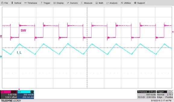
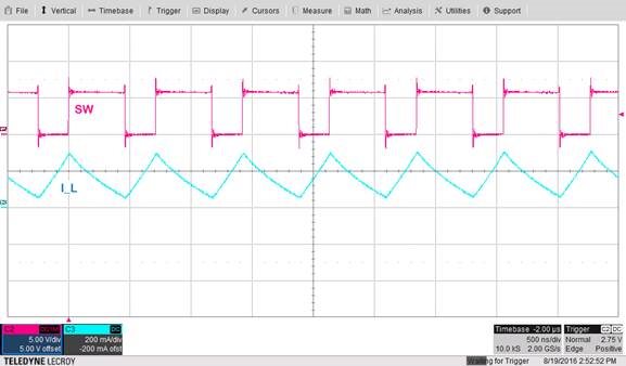
Figure 2 shows the inductor current waveform of a boost converter without saturation. In Figure 3, an inductor with a lower saturation entry point replaces the previous inductor. You can see that for the same DC current the inductor is saturated: the current rises sharply closer to the peaks.
Figure 2: Inductor current
Figure 3: Inductor current – saturation reached
Apart from the DC current that flows into the inductor, the ambient temperature also influences the saturation entry point. Inductor manufacturers specify the saturation current for the typical temperature in data sheets, and not considering this might lead to having the wrong inductor in your application. The inductance vs. current curve changes over temperature, as you can see in Figure 4. Therefore, the saturation current will vary as well with temperature and will be reduced for higher temperatures.
Figure 4: The influence of temperature in saturation current
The importance of saturation current lies in the fact that saturation of the inductor for a DC/DC converter can lead to destructive consequences. When the inductor enters saturation, it can store less energy and the ripple current increases – meaning that the efficiency will be reduced. At this point, the inductor is behaving more like a resistor than an inductor. In addition to that, high current peaks will appear on the switch node because of the drop in inductance value occurring with saturation. This can damage the inductor itself or other components and create noise. Stability issues can result from the inductance decrease as well.
When selecting an inductor (after defining the parameter values), I recommend taking advantage of the tools available on inductor vendors’ websites, which enable you to compare inductors in the context of parameters such as saturation current, ambient temperature and total losses. Then, a rapid check in the lab of the inductor current under the actual operating conditions will surely help you determine whether the selected inductor is saturating or not. For more help on selecting an inductor for a buck converter application, please download our application note on selecting inductors for buck converters.
Additional resources:
- Watch this video and learn the basics of inductor terminology.
- Read the last waveform audit: Waveform audit: my boost converter has an off-ramp!
- Explore TI’s portfolio of DC/DC converters.
- Decode your DC/DC datasheet with our DC/DC datasheet blog series.

