Measuring on an oscilloscope output ripple and dynamic response on low voltage (~1V) / high current (30-150A) power supplies has been a challenge with each new setup creating its own set of errors. Errors due to the probe pigtail ground have been addressed with the oscilloscope “tip-and-barrel” approach or a dedicated impedance-matched voltage-sense cable. However, even with the best probing methods, it’s possible to get distorted output measurements, especially when applying or removing a dynamic load. I’ve seen two sources of error:
- Ground loops caused by currents through the grounded side of the voltage probe going to oscilloscope ground and the oscilloscope’s AC plug ground connection.
- When measuring more than one signal on the same oscilloscope at the same time, the oscilloscope may be grounded at more than one point to the test setup, introducing errors in all channels. This is especially true when trying to display both output voltage and output current on the same oscilloscope.
Let’s look at the first error source in more depth. If the oscilloscope is grounded to the same building ground wiring as the power source or output load, then a change in load can drive currents in the oscilloscope’s probe ground sheath. This current, multiplied by the sheath’s impedance, will show up as a voltage on the oscilloscope itself and can drown out the actual ripple you’re trying to measure. Other sources of this ground-sheath current include the noisy lab power source itself, even with a static load and an external signal generator.
I have seen these methods eliminate or reduce ground-sheath current:
- Pass the AC cord to the signal generator with several turns through a toroid ferrite.
- Place the dynamic load on the test board itself instead of using the external electronic load.
Other options include using a battery-powered oscilloscope or an oscilloscope with isolated inputs.
The second source of error, the oscilloscope ground conflict issue, isn’t as well known. It is also the cause of distorted power-supply dynamic load response measurements when using the oscilloscope to show both the output voltage and dynamic load current change, or more than one output voltage at the same time. With more than one low-voltage measurement, the oscilloscope ground will be tied to the test setup at more than one point through more than one probe. The actual oscilloscope ground will then be the “average” of the grounding connections.
For example, if there is a +40mV difference between the power-supply ground at the voltage-monitor point and the current-monitor point, and the ground connections of both monitoring points are of similar quality, then a ~+20mV error will appear at the voltage-monitor point and a -20mV error will appear at the current-monitor point. The current monitor usually has several hundred millivolts of signal vs. the 50mV or less allowable output-voltage overshoot/undershoot in low-voltage applications such as computer core power.
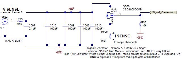
Figure 1 is an example of a power-supply output test setup where I monitored the response to a large step load on the output and also had the oscilloscope monitor the dynamic load current across a low-value resistor. I used a signal generator to drive the desired step load size with the desired rise and fall times and sensed voltage with a 50Ω cable attached to J502. The 50Ω R527 dampens any reflections on the cable. I used the tip-and-barrel approach to sense current across R500 with a 10x oscilloscope probe.
Figure 1: Test setup
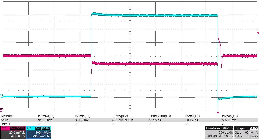
Figure 2 shows both the sensed voltage and sensed dynamic load current on the same oscilloscope when applying and removing a 59A pulse load.
The application requirements are that VOUT (the red trace on the oscilloscope/J502 in Figure 1) stays within a 855-945mV range under both load step and load dump. Dynamic current is measured across a 10mΩ resistor (R500 in Figure 1) tied to ground and is the green trace shown in Figure 2.
Figure 2: Step-load and load-dump response from 2A to 61A with dynamic current sense while connected to the oscilloscope
Based on Figure 2 and looking at the channel two red trace showing Vout, the voltage output drops to 861mV when applying the load step, then stabilizes at 889mV with the higher load. Upon removal (dump) of same added load, the voltage output peaks at 940mV before stabilizing at 900mV. Thus, the voltage output stays within the 855-945mV limits, and the test “passes.” Looking at the channel three green trace showing the voltage across the 10mΩ current sense resistor, the dynamic load goes from 0A to 593mV/10mΩ, or 59A and back to 0A.
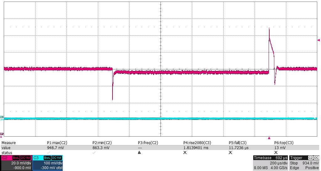
Disconnecting the current-sense probe from the oscilloscope shows a different voltage waveform on the output. See Figure 3.
Figure 3: Same dynamic response at VOUT with the current sense disconnected from the oscilloscope
Based on Figure 3 and looking at channel two red trace showing output voltage, the voltage output drops to 863mV when applying the load step, then stabilizes at 896mV with the higher load. Upon removal (dump) of the same added load, the voltage output peaks at 949mV before stabilizing at 900mV. Thus, the output goes above the 945mV limit and the test “fails.”
Off-site test experience
Testing with an off-board “load slammer” and trying to monitor both the output voltage on the main board and the dynamic load on the slammer made the dynamic response look very poor. When I removed the current-sense connection from the oscilloscope, I saw a good dynamic response. There, the current-monitor connection created a false fail.
If you are going to monitor both current and voltage on the same oscilloscope, you will need either an oscilloscope with fully isolated inputs or a dynamic load with sense resistor ground right at the voltage-ripple monitor. For the first option, you’ll also need two sets of differential probes with good input isolation.
Stay tuned for an upcoming blog highlighting a design with a dynamic load test interface which will allow monitoring both voltage and dynamic current at the same time without differential probes.
Additional resources
- Watch Power Tips videos to help with your design challenges.
- TI Power Seminar White Papers


