In part one of this series, we looked at how to suggest an appropriate cross reference for a FET when the end application is unknown. In this blog and those upcoming entries in this series, we’ll start to look at what specific considerations to take into account for a certain end application, starting with FETs that will be used in the end application to drive a motor. Motor control is a large (and rapidly growing) market for 30V-100V discrete MOSFETs, particularly for a number of topologies that drive DC motors. Here, I’ll focus on selecting the correct FETs to drive brushed, brushless and stepper motors. While there are very few hard rules and a potentially infinite number of different approaches, I hope that this post will give you some idea where to start based on your end application.
The first and probably easiest choice to make is what breakdown voltage you require. Because motor control tends to be lower frequency and therefore causes lower ringing compared to power-supply applications, there is a tendency to be a bit more aggressive with the margin between the input supply rail and the breakdown of the FET (often at the expense of using a snubber) in order to obtain a lower-resistance FET. But in general, a 40% buffer between BVDSS and the maximum input voltage, VIN, is not a bad rule – give or take 10% depending on how much ringing you anticipate and how much you are willing to dampen said ringing with external passive components.
Selecting a package type is perhaps the most critical decision, and depends entirely on the design’s power-density requirements (see Figure 1). Below 2A, FETs are most often (but not always) absorbed into the driver integrated circuit (IC). For stepper motors and low-current brushed and brushless applications below 10A, small-form-factor PQFN-type devices (SON 2mm by 2mm, SON 3.3mm by 3.3mm) offer the best power density. If you’re prioritizing low cost over higher power density, older SOIC-type packages might get the job done, but will inevitably take up more printed circuit board (PCB) space.
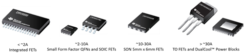
Figure 1: Various packaging options for driving different motor currents (packages not shown to scale)
The 10A-30A space that small battery-powered tools and home appliances occupy is the sweet spot for 5mm-by-6mm QFNs. Above that, higher-current power and gardening tools tend to either parallel multiple FETs, or they implement bigger packaged devices like D2PAK or through-hole packages like the TO-220. These packages can house more silicon, enabling lower resistance, higher current capability and better thermal performance. Mounting through-hole packages on large heat sinks also dissipates even more power.
The question of how much power a device can dissipate depends just as much on the thermal environment of the end application as it does on the package of the FET. While surface-mount devices generally dissipate most heat through the PCB, you can attach other packages like the aforementioned TO-220 or TI’s DualCool™ power block devices (Figure 2 below) to a heat sink in order to pull heat away from the board and increase the maximum power that the FET can dissipate.
The last thing to look at is what resistance you should be targeting. In some ways, selecting a FET to drive a motor is simpler than selecting a FET for a power supply because lower switching frequencies dictate that conduction losses dominate thermal performance. I don’t mean to imply that you can entirely neglect switching losses in PLOSS estimations. On the contrary, I have seen worst-case scenarios where switching losses can represent up to 30% of the total PLOSS in a system. But these losses are still secondary to conduction losses and therefore shouldn’t be your first consideration. Power tools designed around ultra-high stall currents generally tend to push the FETs to their maximum thermal capability, so the lowest-resistance devices in a given package are a good place to start.
Lastly, I would like to revisit the power block devices mentioned prior. The 40V CSD88584Q5DC and 60V CSD88599Q5DC are two vertically integrated half-bridge solutions housed in a single 5mm-by-6mm QFN DualCool package (see Figure 2). Doubling down on the low resistance per footprint offered by traditional discrete 5mm-by-6mm devices while offering an exposed metal top for the application of a heat sink, these devices are uniquely suited to handle higher currents (40A and more) in space-constrained applications.

Figure 2: Stacked die power block mechanical breakdown
Before resorting to a bulkier TO package for your design, it might be worth it to run the numbers on one of these power blocks to see if you can save some serious space on PCB footprint and heat-sink size. Questions? Please feel free to leave a comment below.
Additional resources
- For more information on CSD88584Q5DC and CSD88599Q5DC power blocks and how they meet current market demands, see my other blog post, “Demand for higher power density drives innovative power tool solution.”
- For information about power dissipation and thermal performance through a QFN, check out my colleague Manu Balakrishnan’s blog posts:
- “Protect your BLDC motor drive with cycle-by-cycle current limit control – part 1.”
- “Protect your BLDC motor drive with cycle-by-cycle current limit control – part 2.”
- In “How to minimize MOSFET conduction loss in battery-powered motor drives,” he discusses how to minimize conduction losses through the FET.