Ever-evolving technology demands smaller, modular, performance-driven solutions. Power modules contribute to very small solution sizes and smaller board-space requirements, but can come at the cost of design flexibility. Many newer DC/DC regulators and power modules internalize loop compensation or feature operating architectures that do not require loop compensation, making them very easy to use. But in some cases, that could reduce your ability to fine-tune design performance.
For example, as process technology advances, processors require tighter voltage accuracy and lower core voltages. Table 1 is a chart from a field-programmable gate array (FPGA) datasheet stating that the recommended operating conditions for the VCCINT rail are 1V, plus and minus 30mV. The manufacturer doesn’t recommend any voltage outside of this 3% range because the processor could behave unexpectedly outside this voltage window. Thus, you may have to increase the capacitance at the output of DC/DC converters to meet the 3% range during load changes.
Symbol | Min | Typ | Max | Units |
FPGA logic | ||||
VCCINT | 0.97 | 1.00 | 1.03 | V |
0.87 | 0.90 | 0.93 | V | |
VCCBRAM | 0.97 | 1.00 | 1.03 | V |
0.87 | 0.90 | 1.03 | V | |
Table 1: Recommended operating conditions for a field-programmable gate array (FPGA)
While small capacitance increments are allowable, much larger amounts could negatively affect the module’s load transient response. To optimize transient response, designers typically add a feedforward capacitor (CFF) in parallel with the upper feedback resistor, as shown in Figure 1. In the frequency domain the addition of CFF creates a zero, which increases bandwidth and improves the transient response time.

Figure 1: Feedback divider with feedforward capacitor CFF
Unfortunately, while CFF creates a zero to help increase bandwidth, it also creates a subsequent pole as a product of CFF and the parallel combination of feedback resistors. This pole can negate the benefits brought about by the zero of the CFF. Since CFF adds a zero and a pole, which may not be too far apart in frequency, the choice and calculation of CFF becomes tricky. The right CFF value will help the situation, while a wrong CFF value will bring no improvement and will just be a useless addition to the bill of materials (BOM).
TurboTrans™ technology, shown in Figure 2, improves the loop response by adding just one resistor (RTT). Adding an RTT resistor enables you to optimize the feedback loop easily using a resistor outside of the module. By adjusting the TurboTrans resistor, you can optimize the zero and midband gain (AVM) of the compensation stage as required. There are no side effects like that of a consequent CFF pole with the use of a RTT resistor.

Figure 2: Power module with TurboTrans technology
The RTT resistor is nothing but an additional series resistor in the Type II compensation scheme. This additional RTT resistor doesn’t require in-depth knowledge of loop compensation techniques because, like for any other power module, the data sheet will provide an equation to calculate the right value. Your calculation will simply depend on the amount of total output capacitance. The RTT will compensate for any additional capacitance at the output, and the load transient response will remain spectacular.
Let’s use TI’s TPSM84824 to show how TurboTrans technology helps achieve a fast transient response. In order to meet the 3% range (recalling Table 1), the only thing you can do in the absence of TurboTrans technology is increase the output capacitance. As you can see in Figures4 and Table 2, capacitance increments have little effect on the voltage droop. That’s because with increasing output capacitance, the overall bandwidth of the regulator reduces considerably (as shown in Figure 3). This makes the loop slow and increases the time required to react to a load transient. Consequently, even with a large value of output capacitance, the power module still cannot maintain less than 30mV of voltage droop.

Figure 3: Gain curve with different output capacitance
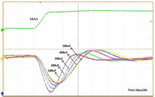
Figure 4: Transient response with different output capacitance
Output capacitance (µF) | Crossover frequency (kHz) | Voltage droop (mV) |
188 | 41.0 | 114.6 |
288 | 31.3 | 103.2 |
388 | 26.0 | 92.4 |
488 | 22.8 | 86.4 |
588 | 20.5 | 82.2 |
Table 2: Voltage droop with different output capacitance
The situation improves if you use the TurboTrans feature. By adjusting the TurboTrans resistor, you can easily get 17.4mV of voltage droop, as shown in Figure 5.

Figure 5: Transient response with TurboTrans technology
As the experimental results show, TurboTrans technology enables you to considerably improve the performance of your power module. Depending on the application, this feature can also help reduce the overall capacitance at the output, thus reducing system cost and size.
Additional resources
- Learn more about TI DC/DC power modules.
- Read the application report, “LMZ1050x/LMZ1050xEXT SIMPLE SWITCHER® Power Module – Quick Compensation Design.”