Image may be NSFW.
Clik here to view.
One key metric to determining power-module reliability is the storage temperature rating. When selecting a module, you need to be sure that the module manufacturer is independently verifying the stand-alone inductor component used in the power module. Inductor qualification tests are not standardized across companies and quantities, and ratings that appear on data sheets can be inconsistent.
High-temperature storage (HTS) testing involves exposing the device to a rating temperature for 1,000 hours, and then checking for consistent characteristics before and after the exposure. All TI power modules are rated to a storage temperature of 125°C or above, meaning that the devices are guaranteed to maintain performance (efficiency) even after exposure to high temperatures.
In addition to this test in the module qualification regimen, module inductor components are pre-screened to ensure that they will meet a storage temperature requirement of 150°C as stand-alone components. Although inductor data sheets often cite a storage temperature, TI’s power-module team has found that some inductors rated to a specified storage temperature on the data sheet may not be suitable for use in a particular switching-converter application. Without qualifying the inductors before prototype and production, frustration and redesigns may occur.
The reason for this unsuitability is that the thermal aging in the material occurs in some inductors after exposure to high temperatures. This well-known phenomenon may not have previously been much concern if you use your devices below 65°C, but it has a significant effect on devices made to operate at temperatures above 85°C. You can observe the change in material by thermally measuring the losses of the inductor under test currents, or by using the inductor in a switching converter and noting a drop in efficiency, especially in wide Vin or high-output-current devices. Although these two test methods may be complex, you can also determine thermal aging with two straightforward measurements, which TI uses to qualify and select inductor components.
Figure 1 shows two simple measurements that indicate HTS failure. Samples from four different inductor vendors are evaluated at 150°C with measurements every 168 hours, showing significant drops in both quality factor Q at the switching frequency, and shunt or core resistance measured without biasing the device. The inductors that fail this test demonstrate high losses post-exposure when used in a buck-converter application, in spite of a lack of any visually observable changes, or change to direct current resistance (DCR) or L0. This impact would be more significant in a wide Vin device and/or a device with a high output current simply due to the increased leakage current flowing through the now-reduced shunt resistance of the inductor.
In the evaluation shown in Figure 1, feedback from TI enabled one vendor to sample a second device, using an improved magnetic material that did not demonstrate thermal aging (vendor A2 in Figure 1), which was then chosen for the TI module. The details of the exact revision made to the device are generally proprietary, but it is likely that the revised device had a different material formula than the first device.
Image may be NSFW.
Clik here to view.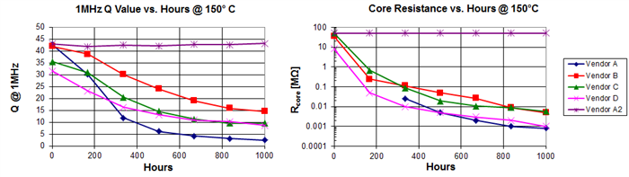
Figure 1: Quality factor and core resistance as a function of test time for several inductor devices
Conclusion
TI has developed an independent inductor testing regimen for every inductor component selected for use in a power module. The HTS test is a critical aspect of TI reliability evaluation, enabling us to evaluate whether an inductor may exhibit significant core losses once exposed to high temperatures for an extended period.
This test is significant, since the deficiency may not be obvious when measuring only the inductance and DCR before and after exposure. Qualifying the inductor component by itself is critical to ensuring a reliable switching converter without revisions and reliability issues later in the design cycle.
Image may be NSFW.Clik here to view.
