Field-programmable gate arrays (FPGAs) are increasingly complex system-on-chips (SoCs) that include not just programmable logic gates and random access memory (RAM) but also analog-to-digital converters (ADCs); digital-to-analog converters (DACs); and programmable analog features and signal-conditioning circuits that enable high-performance digital computations in servers, network-attached storage (NAS), enterprise switches, oscilloscopes, network analyzers, test equipment and software-defined radios.
The Intel® Arria 10 SoC is such an FPGA. TI has a fully-compliant Arria 10 GX power solution in our reference design library. Arria 10 devices are the only high-performance FPGAs and programmable SoCs developed on Intel’s 14nm Tri-Gate process, offering up to 70% lower power compared to the previous generation.
To reduce power, a Smart Voltage ID (SmartVID) interface offers a large number of very small voltage-reduction steps that are programmable into the FPGA’s nonvolatile registers in order to reduce the power dissipation of the chip.
The SmartVID feature compensates the process variation by narrowing the process distribution using voltage adaptation. Instead of a constant voltage, SmartVID-enabled devices opportunistically adjust the device voltage for optimal power – while at the same time meeting performance goals. To save power, Smart VID reduces the voltage on devices with performance beyond the specification requirements.
SmartVID enables the FPGA core power regulators to provide Arria 10 devices with lower VCC and VCCP voltage levels in a closed loop system while maintaining the performance of the specific device speed grade. These voltages can vary between 0.83V and 0.975V, in 5mV, 10mV, or 15mV increments.
When using SmartVID, Arria 10 devices must be powered up to a default voltage level for both VCC and VCCP. The VCC and VCCP rails will first wake up to a default voltage of 0.9V. After determining the voltage ID value and communicating this value to the external voltage regulator, the VCC and VCCP voltage values will change according to the determined VID value. Typically they will vary from 0.85V to 0.9V (For more information, see Intel AN11 Application Note)
One of the SmartVID communication interface options between the Arria 10 FPGA and the external Vcore voltage regulator is the two-wire PMBus digital serial interface at a 400kHz clock speed as described in Intel’s “AN711 Application Note: Power Reduction Features in Intel Arria 10 Devices”. In a PMBus system, the Arria 10 FPGA acts as a PMBus master or a slave – whatever you prefer.
If the Arria10 is the PMBus master, it will communicate the new Vcore value via PMBus to the Vcore voltage regulator (acting as the PMBus slave) in a range between 0.83V and 0.975V using the standard PMBus command “VOUT_COMMAND” – 21h hex code. The PMBus master uses the VOUT_COMMAND instruction in the data format retrieved from VOUT_MODE to write voltage ID values to the voltage regulator. The PMBus Vcore regulator will then set its output voltage to the new commanded value as dictated by the FPGA with a resolution of 5mV, 10mV, or 15mV depending on the power reduction required. Table 1 lists the SmartVID power requirements.

Table 1: Smart VID regulator requirements (source: “Arria 10 handbook”)
Figure 1 shows the Smart VID implementation with the external Voltage Regulato
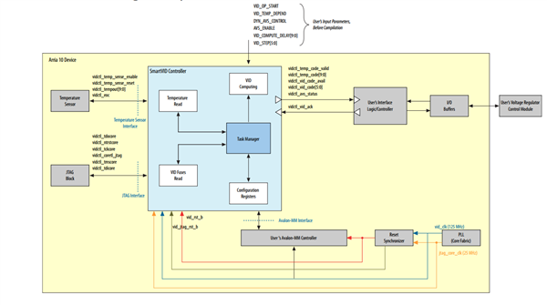
Figure 1: Arria 10 FPGA Smart VID interface with external Voltage Regulator: “Smart VID Controller IP Core User Guide"
The regulator(s) must meet the static, ripple and dynamic power tolerances listed in the “Arria 10 GX, GT, and SX Device Family Pin Connection Guidelines” during all phases of power delivery after reaching the boot voltage. The VCC and VCCP voltage regulator supply tolerance is ±30mV.
To implement SmartVID with PMBus, you must enable PMBus in the FPGA with Quartus Prime software version 15.1. Only the Arria 10 VCC and VCCP (core) rails can use SmartVID.
Figure 2 shows the TIDA-01419 reference design power delivery to the Arria 10 GX FPGA (10AX115U145IVG part number with high utilization) VCC and VCCP rails via the PMBus SmartVID interface.
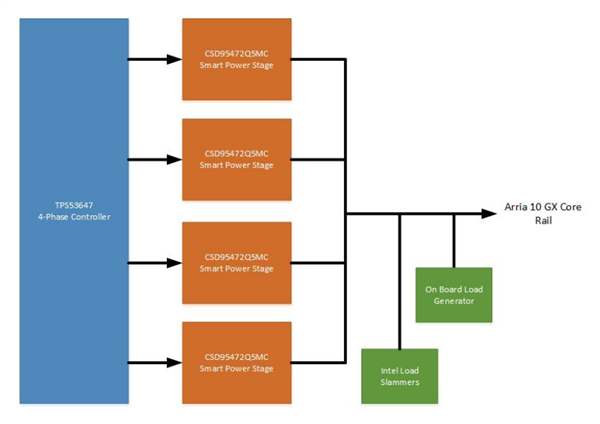
Figure 2: Intel Arria 10 GX (10AX115U145IVG part number with high utilization) power solution with SmartVID PMBus implementation for VCC/VCCP rails - TIDA-01419 reference design
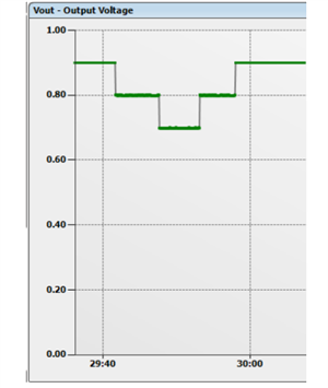
Figure 3: Intel Arria 10 GX TIDA-01419 reference design Smart VID adjustment via PMBus
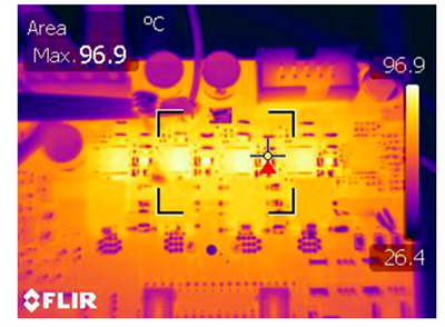
Figure 4: Intel Arria 10 GX TIDA-01419 reference design thermal performance (25degC ambient temperature, no airflow, no heatsinks, 12-Volts Input, 0.9-Volts/100-Amperes
The TI Arria 10 GX TIDA-01419 reference design uses the TPS53647 4-phase, driverless, PMBus, pulse-width modulation (PWM) controller with capability for up to 4-phase operation. The controller utilizes DCAP+™ control mode for ultra-fast load transient response, very easy loop compensation, and excellent stability irrespective of input voltage, phase count, or load current. It offers extensive parameter pin-strapping, and PMBus programming, control and monitoring of input/output voltage, current, temperature and power, as well as system faults. Since input and output power are monitored real-time, instantaneous efficiency calculations of the high-current VCC/VCCP rails can be performed.
The TPS53647 is paired with TI’s CSD95472 smart power stages, which include high-performance NexFET™ gate drivers and high- and low-side NexFET power MOSFETs stacked on top of each other in a PowerStack™ packaging configuration for high efficiency, optimal thermal performance, easy heat sinking and high power density. The smart power stages include temperature-compensated, bi-directional current sensing for reducing inductor size and cost per phase. The PowerStack™ package employs a single large GND pad on the bottom of the IC for easy top-layer printed circuit board (PCB) layout, and direct thermal sinking into the PCB internal ground planes for excellent multiphase converter thermal performance.
The TPS53647 is a pin-to-pin device to the TPS53667 6-phase controller which is also available in case a higher-phase-count design is needed to manage the thermals even better and reduce the capacitor and inductor size.
According to the Arria 10 GX documentation “A10 handbook, page 317” power up and down sequencing is needed.
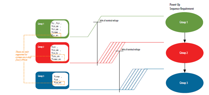
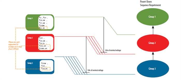
Figure 5: Intel Arria 10 GX power up and down sequencing, Arria-10/a10_handbook.pdf
TI has a complete family of PMBus sequencers with monitoring, margining, and Blackbox logging that can be used as companion devices to the Arria 10 GX multiphase buck dc-dc converter.
So if you are designing with Intel’s Arria 10 GX FPGAs and looking to implement SmartVID via PMBus, consider TI’s PMBus multiphase DC/DC and sequencer solutions for the VCC and VCCP rails.
Additional resources
- TIDA-01419 Intel Altera 10 GX reference design
- Review TI’s PMBus power-device portfolio on the Digital Power Control Solutions portal.
- Find the appropriate PMBus sequencer here PMBus Sequencers
Source: Intel Corporation (www.Intel.com)