Inductors are an essential component of switching voltage regulators and synchronous buck converters, as shown in Figure 1. In all switching regulators, the output inductor stores energy from the power input source when the MOSFETs switch on and releases the energy to the load (output).
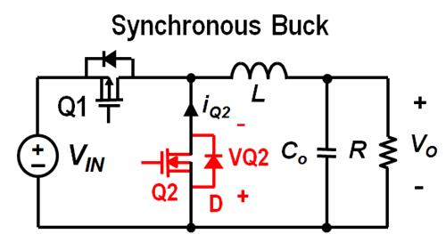
Figure 1: Synchronous buck DC/DC converter
You should select inductors to manage output capacitor size, load transients and output ripple current. There are benefits of both low and high inductance values.
The benefits of low inductance include:
- Lower DC resistance (DCR), which is inherent in the inductor wire, and which affects ripple and power loss.
- Higher saturation current, for higher output-current capability.
- Higher slew rate (di/dt), which improves load transient response and reduces output capacitance for a given load transient.
The benefits of high inductance include:
- Lower ripple current, which in turn reduces:
- AC losses (inductor skin effect).
- MOSFET root-mean-square (RMS) current.
- Output capacitor RMS current.
- Output capacitance for an equivalent output ripple.
- Continuous inductor current over a wider load range.
Equation 1 calculates the output inductor value:

where L is the output inductance, VOUT is the target output voltage, VIN(max) is the maximum input voltage, FS is the buck converter switching frequency and IRIPPLE is the target output ripple current.
I recommend sizing the ripple current for 10% to 30% of full load. Plugging values into Equation 1, Equation 2 shows the output inductance calculation result:

In this case, I selected the PG0077.801 inductor from Pulse Electronics. Table 1 shows its relevant parameters.

Table 1: PG0077.801 inductor parameters (image courtesy of Pulse Electronics)
It is important to check the inductance vs. the load (bias) current, as inductance decreases with increasing current. Then you can determine what the actual inductance is at the target load current.
If you assume 15A of continuous output current, the actual inductance is 0.83mH, as shown in Figure 2.
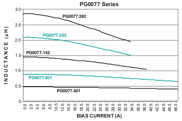
Figure 2: Inductance vs. current (image courtesy of Pulse Electronics)
Once you know the actual inductance value, you can recalculate the ripple and RMS currents. Equation 3 recalculates ripple current:

Equation 4 recalculates RMS current:

You can also calculate the inductor losses. Total inductor losses are winding losses and core losses, expressed by Equations 5 and 6:

where K1 = 13.77 x 10⁻⁹ , K2 = 39.4, FSW = 500kHz, DI = 3.32A (the calculated ripple current) and PCORE = 0.983W.
In this example, the total inductor power loss is 0.294W + 0.983W = 1.277W.
There are many inductor types to choose from, but most buck DC/DC converters typically use ferrite drum and iron powder toroid inductors. So when designing a buck converter, keep these inductor selection criteria in mind for a high-performance, stable and reliable design. Check out TI’s buck converter and buck controller selection tables for a variety of buck DC/DC solutions.